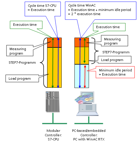
The figure below shows the structure of the STEP7 programs and the cycle times in the different IO controller types:
STEP 7 program:
The STEP7 program consists of two parts:
It contains STEP 7 blocks for the automation of measurement and for communication with the distributed stations.
The user program performs the following tasks:
The load program has not specific tasks and fulfills no specific function by itself.
It is merely used to increase the size of the STEP 7 program and to thus extend the cycle time.
Differences between S7-CPU and PC-based controller:
PC-based IO controllers are normally used, if data processing and/or other HMI functions are to be performed in addition to the control tasks. These functions – which are not included in a classical PLC in this way – also require time in the processor. To ensure sufficient processor time, the PC system must be configured accordingly, so that the control task leaves some time for the processor.
For this reason, the "minimum sleep time" for this measurement was set in compliance with the processing time of the control task. Within this minimum sleep time, no control tasks are performed. However, communication tasks initiated by the PC-based control function can also be performed. This also explains the PN reaction times measrued with PC-based systems.
To achieve a practical PC workload of approx. 50 %, the minimum sleep time parameters for all measurements are defined as follows:
minimum sleep time = Execution time!
Example
|
Criterion |
Sequence for standard PLCs |
Sequence of PC-based systems |
|---|---|---|
|
Runtime of the whole STEP7 program: 10ms |
Actual cycle time of theSTEP7 program. 10ms |
Actual cycle time of theSTEP7 program. |
|
Effect on the PN reaction time (*) included. |
The PN reaction time includes at least 10ms. |
The PN reaction time includes at least 5ms. |
(*) For details about the minimum, typical and maximum PN reaction times, please refer to chapter 3.3..